3.1 - Cutting and Grouping Images
Before we can begin mounting stereo pairs, the uncut strip of film must be cut into individual frames, and the left and right pairs of each photo identified. This is most easily done using a lighted film cutter, such as those sold by Reel-3D, but many people have very good success using only a sharp scissors and a light table. But first, let's look at how an uncut strip of film is arranged. We'll use a European format for this example (For Realist format, there are three pairs interleaved): Warning: Which side of the film the "exposed leader" (shown below on the left) appears on depends upon camera construction. The FED, like most 3D cameras, feeds from left to right when viewed from the camera back, so the exposed part of the leader is shown properly here on the left (allowing for the "upside down" images produced by the camera lenses). Other cameras (for example, the Realist 45) have the film transport from right to left, and the film produced will have the leader on the opposite side of that shown here. The drawing as shown here is correct for the vast majority of 3D cameras.
Sample exposed European format film strip - FED camera
"But wait," you say, "you've got the 'Left' and 'Right' mixed up!". No - it shows up on film this way because the camera lenses reverse an image when a picture is taken. If you were to place this bit of film as it was in the camera, you would rotate it 180 degrees so that the exposed leader was to the right, making the pictures upside down.
OK - now let's cut the film and separate the pairs:
- Cut the film down through the middle of the dark line between each exposure. This is an excellent time to separate the cut film chips into their stereo pairs as well. How you do this depends upon the format you are shooting. For Realist slides, there are two exposures from "other" shots between each stereo pair, while for European format, every other film chip goes together. As much as possible, leave an equal amount of the black band between the exposures on each chip. If you are cutting Realist format, the black band may be very small, and in some cases the exposures will even overlap. In this case, do the best you can to split the difference.
- For beginning stereo mounting, it is recommended that you cut only enough film chips to get your first pair, then mount it, and continue. This way it is much easier to avoid mixing up film chips than it you cut the whole roll at once, especially if you have many shots which are very similar.
- Now is also a good time to identify the left and right film chip of each stereo pair. Use the way the film chips are arranged before cutting, according to the following diagram:
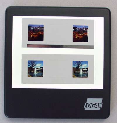
Cutting and sorting slides (shown: European format)
Note: If you get left-right sides of a pair mixed up, you can refer to Appendix A for other ways of determining the left and right film chips.
What we have accomplished: We now have our first two stereo pairs (three, if you're cutting Realist format film, or the whole roll, if you're gutsy) cut, and have identified the left and right images of each pair. They should be sitting in front of you on the light table, "normally" oriented.
3.2 - Placing the Film Chips In the Mount
Now it's time to place the first pair in a slide mount. The specific technique will vary for the different types of mounts. If you are new to slide mounting, slip-in mounts are by far the easiest to learn. If you are using RMM's new horizontal style slip-in mounts, see the separate detailed instructions for using them. For other types of mounts, continue reading below.
Cardboard Mounts
Now it's time to place the first pair in a slide mount. First, place the slide mount on the light table over the alignment gauge. In the following drawing, the alignment gauge will NOT be shown, to make the drawing clearer.
Placing the film chips in cardboard mounts (shown: European format)
On any mount style, but especially if you are using mounts which do not have alignment tabs, shift the left film chip up/down and left/right until you are pleased with the composition. Realist film chips allow very little leeway, while mounting twin-full-frame-35mm chips in European or Realist mounts provides lots of horizontal room. The idea here is to align the film chip in the left opening so that it is horizontal with respect to the mount opening, and so that a pleasing composition results.
Secure the film chip (the left one) that you have just oriented with one or two small bits of tape. Mylar® tape is recommended.
Aluminum Masks
First, determine which direction the film curls. Most films have a natural curl (typically between the sprockets) even after being flattened or reverse rolled. If the slide will be sandwiched in glass, the film chips should be installed so that the natural curl of the film holds the center away from the glass (towards the aluminum mask). This is especially important with Albion masks, which have a single aluminum layer, as opposed to the EMDE masks, which have two aluminum halves which are folded like a cardboard mask.
With the film chips still sitting on the light table, determine whether the film chips bow up in the center, with the edges sitting on the table, or at the edges, with the center sitting on the table. If they sit with the center bowed up, place them in the mount face down (as in the A section of the figure below), and if they bow down, place them in the mount face up (as in the B section of the figure below).
Note: When sliding the film chips under the tabs, you may find it easier to flex the film chips slightly in the center and slide the top and bottom under their respective tabs. If you try to slide the film chip in from the end of the channel, you risk scratching the emulsion on the sharp edge of the hole. Which method you choose, however, is a matter of personal preference.
Placing the film chips in aluminum masks (shown: European format, Albion mask)
3.3 - Using the Alignment Guide
Setting the Stereo Window - "Mounting to the Window" Method
Note: This section documents the most common method of setting the stereo window. It is recommended for beginners, due to its relative ease. Other methods can give a more consistent slide show - see Appendix B for a description of the various methods of setting the stereo window.
Now comes the fun part. In slide mounting, the horizontal relationship of the two film chips determines "how close" an object appears to you. Moving the film chips closer together will cause all objects in the scene to appear to be "closer" to you; moving the chips apart will cause the scene to appear farther away.
Any object whose images in the left and right film chips are exactly the same distance apart as are the apertures of the stereo mount, will appear to be located "at the stereo window." In other words, something which is 3mm from the left edge of the opening on the left film chip and also 3mm from the left edge of the opening on the right film chip will appear to be at the stereo window.
The vertical guide lines on the Realist mounting gauge help determine the nearness of an object. There is a single vertical line on the left side, and two vertical lines (one labeled "near" and one "far") on the right side.
Important: An unfortunate and confusing situation exists with mounting gauges that have been sold for many years. You may have seen gauges labeled "Realist (5P)" and "European (7P)." Forget that you ever read those descriptions! What matters is the aperture spacing, not the aperture width! For almost all mounts on the market today, the "European" format mounting gauge (62.1 mm spacing) is the better one to use...even for Nimslo format stereo slide mounts! Only use the gauge set for 62.4mm spacing when using the traditional 5P heat seal mounts (with the light blue or dark green interior). Use the 62.1 mm alignment gauge for all new style heat seal mounts (yellow register inside), self-stick mounts, precision tape-shut ("Spicer") mounts, and RBT mounts.
After selecting the correct mounting gauge, choose an object in the photograph for which you want to set the stereo window. Pick the closest object you can. I often use a pebble, blade of grass, the edge of an object --- something which is well defined and appears in both film chips, but it must be the nearest object (unless you plan to create a "through the window" effect).
To use the gauge, slide the entire mount left or right until the vertical line on the left of the gauge lines up with your object in the left film chip. Then align the same object in the right film chip with the "near" line by sliding the right film chip back and forth. When the objects in both pictures are aligned, that particular object is at the location of the stereo window. If the object lies to the left of the near line, it will appear to be in front of the stereo window (i.e. will stick out from the screen when projected), while if it lies to the right of the near line, it will be positioned behind the stereo window. A very small change makes quite a large difference, as you can see from the distance between the "near line" and the "far line" on the gauge. (objects positioned at the far line will appear at infinity). So when moving the right film chip to set the stereo window, use great care to position the film chip accurately.
Note: In this discussion we have referred to stereo slide projection, but the same window concepts apply equally well to slides viewed through a hand viewer.
The stereo window is best taught visually. Refer to Shab Levy's online stereo window demonstration (PDF), or our "Stereo Window Tutorial," which includes five Realist-format slides that demonstrate the stereo window.
Eliminating Height and Rotation Errors
Use the horizontal lines on the mounting gauge to check for both height and rotational errors. Height errors occur when objects in one film chip are higher than the other; rotational errors means that one film chip is rotated with respect to the other. Both errors can be corrected by using the horizontal guide lines.
Pick two or three objects in both slides which are in different parts of the slide. As when setting the stereo window, you should choose objects which are small or well-defined enough to be easily distinguished. For example, the tip of a tree branch, the peak of a roof, a small stone, etc.
For each object, pick the horizontal line closest to it. The object should be the same distance from the line in both left and right images.
If, for example, both objects are lower in the right opening, raise the right film chip to compensate. If one object is correct and the other is not, you must rotate the film chip slightly to correct the problem.
Often, minor adjustments will be required both ways. You should repeat checks on both points until you can see no difference in heights of all objects measured. A loupe or other magnifier is of great help in getting this precise enough for good projection. While most projectors have adjustments to compensate for height errors, proper mounting can minimize the need to constantly adjust the projector during a slide show.
Final Check
Finally, re-check the stereo window. If you have made corrections for height and rotation corrections, they may have changed the setting of the stereo window done earlier. Repeat the above steps until both the stereo window and the rotation/height adjustments are correct.
When you are satisfied, secure the film chip in the right mount opening with a couple more pieces of tape. If using aluminum masks, then one strip of tape across both chips could be used. Some people use one strip of tape vertically across each film chip, as the mounting channels hold the film chips in the horizontal direction.
Some mounts leak light where the paper or aluminum is punched up to create the film mounting channel. In this case, a light-blocking tape (Mylar® tape or silver metalized tape) should be used to cover the channels to prevent stray light from being projected. Sometimes this can be accomplished with the same strip of tape that holds the film chips in place.
3.4 - Sealing Up the Mount
How To Heat-Seal Mounted Slides
Heat-seal slides can easily be sealed with a common household iron. An iron with a Teflon or other non-stick surface is recommended. If possible, you should reserve an iron not used for ironing clothes. A small "travel" iron works well.
One of the "tacking irons" mentioned earlier works very well, because it has a pad which is small enough to heat-seal the center area between the film openings without damaging the film chips.
How hot to set the iron is a matter of experience, but initially a "medium" setting should be used. The iron should be hot enough that a section of a mount can be sealed in approximately 2 seconds - any hotter, and you risk damage to the film chips.
Press down with the iron on the edges of the mount and hold until a good seal is obtained. Do not allow the iron to cover the film chips - they will buckle or warp under the heat. You may choose to simply seal the outer areas of a mount, and leave the center area between the film chips unsealed, or carefully, tilting the iron at an angle, seal the center portion also.
It is recommended that you practice on a few "junk" slides before attempting to heat-seal your best work!
Sealing Tape-Shut Mounts
Some people use small pieces of "magic" tape to seal the mounts shut at the bottom (and perhaps the edges). Standard cellophane tape should be avoided due to poor archival characteristics. While magic tape is acceptable, it tends to yellow with age, which may degrade the outward appearance of your mounted slides. Using acid-free Mylar® tape avoids this problem and makes for a very attractive finished mount.
Sealing Aluminum Masks Without Glass
If you are using an aluminum mask without glass, you will want to cover the mount now with a foldover mount (which looks very similar to a tape-shut mount, except that all openings are larger than the openings in the aluminum masks). Fold the mount over the aluminum mask, and tape it shut as you described above for the tape-shut mounts.
Sealing Aluminum Masks With Glass
Now it's time to close up the glass mount. The toughest part is getting all the dust out. Use denatured alcohol to clean the glass surfaces. Setting the glass on a hard surface to clean it will help keep breakage to a minimum. Wearing cotton gloves will help keep oils from your skin from fingerprinting the glass, and also to some extent prevent you from getting cut on the edges of the glass.
Dust the surfaces of the film chips and the inside surface of the glass with a fine, soft brush to remove all the dust. Never touch the bristles of the brush with your fingers, as it will accumulate oils from your skin and carry them over to the film chips and glass.
Sandwich the aluminum mask between the two layers of glass and run one strip of tape across the top edge only. Wipe the dust from the outside of the sandwich and place it in a viewer. Study the slide to find any remaining dust. If you see any, open the sandwich and brush dust out as necessary until no dust can be seen in the image.
The other three sides of the sandwich may now be taped shut. Be sure that whatever you use to clean the glass has thoroughly evaporated before you seal the slide. (This is generally not a problem with denatured alcohol).
Hint: If you see a piece of dust in the viewer, try moving your head from side to side in relation to the slide. The dust may appear to move in relation to the image. If it doesn't, it's on the film. If it moves the same direction as you (in relation to the image), it's on the rear glass. Otherwise it's on the front glass. How much it moves can give you a clue as to which surface it is on.
3.5 - Hints & Tricks
If you want to free up your hands, you can go to the drug store and pick up some $10 or so reading glasses, as high a power as they have. They may take a little getting used to, but the reading glasses allow you to get a lot closer and see a lot finer errors with minimal hassle.
When heat-sealing cardboard mounts, you might try putting a piece of cardboard the same size as the opening over both chips to protect them from heat. You may then be able to simply place the iron over the entire mount. Try this on a scrap slide first!